What it calculates
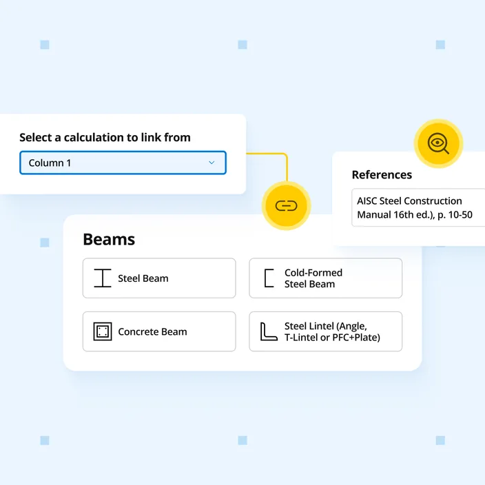
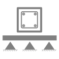
Beam reactions link to connected column and pad footing calculations. Design rectangular and T-section concrete beams to AS 3600:2018 (Amdt 2) with unlimited spans; checks cover positive and negative flexural capacity, shear, and short-term, long-term and imposed load deflection.
Who uses this calculator
Beam reactions link to connected column and footing calculations automatically - change a load once and everything downstream updates. Design rectangular and T-section reinforced concrete beams to AS 3600:2018 (Amdt 2) with the FEA engine handling unlimited supports and loads. Checks cover positive and negative flexural capacity, shear, and short-term, long-term and imposed load deflection.
How it calculates
The Concrete Beam calculator designs rectangular and T-section reinforced concrete beams to AS 3600:2018 (Amendment 2) using limit state design. A live FEA engine resolves internal forces for any number of spans, supports and loads. Flexure, shear and deflection are then checked from those results.
Flexural capacity
Positive and negative moment capacities use the rectangular stress block. The neutral axis depth k_u d is solved by strain compatibility, so the steel stress f_st is computed and capped at f_sy. Top bars, where present, are included as compression steel. For a singly reinforced rectangular section:
phi × M_u = phi × A_st × f_st × (d - gamma × k_u × d / 2)
The stress block factors are alpha_2 = 0.85 - 0.0015 f'c and gamma = 0.97 - 0.0025 f'c, each not less than 0.67. The capacity factor is phi = 1.24 - 13 k_u / 12, kept between 0.65 and 0.85. It drops to 0.65 when Class L reinforcement is selected.
The minimum strength check (Cl 8.1.6.1) passes when either condition is met:
M_u ≥ M_u,min = 1.2 × Z × f'ct,f, or A_st ≥ A_st,min = alpha_b × (D/d)² × (f'ct,f / f_sy) × b × d
where alpha_b = 0.20 for rectangular sections, with a flange-dependent value for T-beams. Where k_u exceeds 0.36 and M* exceeds 80% of the capacity, the calculator also checks for minimum compression steel.
Shear capacity (simplified method, Cl 8.2.4.3)
The concrete contribution is:
V_uc = k_v × b_v × d_v × sqrt(f'c), with sqrt(f'c) not more than 8 MPa
where k_v = 200 / (1000 + 1.3 d_v), not more than 0.15, or 0.15 when at least minimum fitments are provided. The strut angle theta_v is 36 degrees. For vertical fitments, the fitment contribution is:
V_us = (A_sv / s) × f_sy.f × d_v × cot(theta_v)
Inclined fitments add the inclination angle alpha_v to this expression. Total capacity is capped by web crushing:
phi × V_u = phi × min(V_uc + V_us, V_u,max)
phi is 0.7, or 0.75 for Class N fitments that meet the minimum area when web crushing does not govern. Minimum fitments are required where D is 750 mm or more, or where concrete alone is not enough.
Deflection checks
Three deflection results are checked on every span:
- Short-term deflection: under the short-term serviceability combinations, using I_ef for each span
- Long-term deflection: the short-term deflection plus the sustained-load deflection multiplied by k_cs = 2 - 1.2 A_sc / A_st, not less than 0.8
- Imposed load deflection: deflection due to imposed load, checked against its own limit
The effective second moment of area for each span (Cl 8.5.3.1):
I_ef = I_cr / (1 - (1 - I_cr / I) × (M_cr.t / M_s)²), with M_cr.t / M_s capped at 1.0, and I_ef not more than I_ef.max
I_ef.max is I when the reinforcement ratio is at least 0.005, and 0.6 I otherwise. Cantilevers use the support section, and continuous spans average the midspan and support values. Each result is checked against a span/n limit, set separately for interior spans and cantilevers, and an optional absolute limit in mm.
Assumptions
No torsional demands are considered. Prestressing and post-tensioning are not included. Secondary effects on V_uc and load reversal are not considered. Beams are assumed to be enclosed within the building. Detailing such as bar laps, anchorage and hooks is checked separately.