What it calculates
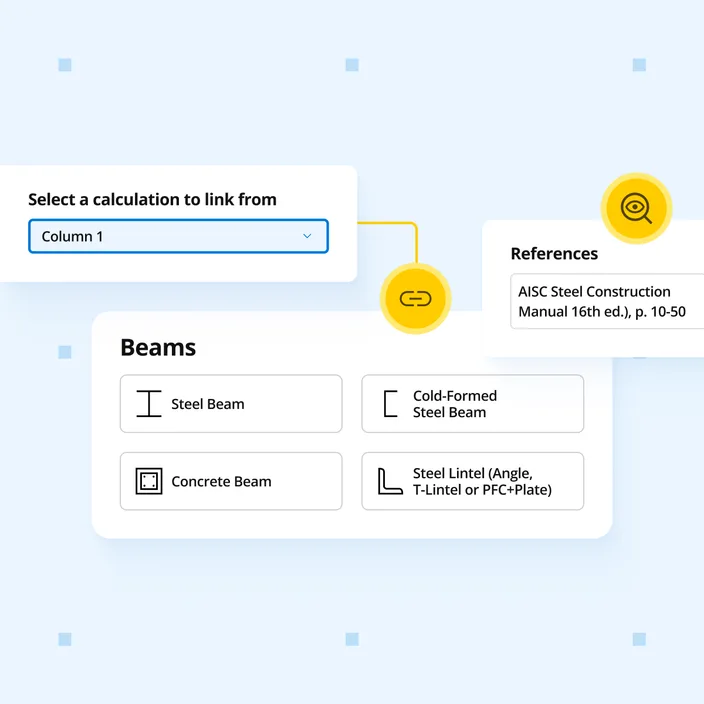
Design a reinforced concrete grade beam acting as a foundation seismic tie between two footings or pile caps to ACI 318-19. Check the seismic tie force in tension and compression, the Cl. 18.13.4.4 dimension and tie spacing limits, flexure and shear from soil overburden, and the axial interaction checks. Column loads link in from the column calculations on each side.
Who uses this calculator
Structural engineers tying two footings or pile caps together in a higher Seismic Design Category, instead of sizing the tie by hand. Column loads link in from the column calculations on each side, so the tie force follows any change. Seismic ties only, not gravity grade beams between piers.
Replaces roughly 2 to 3 hours of hand calculation per grade beam, covering tie force derivation, tension and compression checks, soil overburden flexure and shear, and the combined seismic interaction checks.
How it calculates
The calculator designs a reinforced concrete grade beam that acts as a foundation seismic tie between two footings or pile caps. The tie force acts in both tension and compression, and the beam also carries flexure and shear from the soil above it.
Column loads and the seismic tie force
You enter the unfactored loads that the left and right columns deliver to their footings, or link them from column calculations. Each set of loads runs through the strength load combinations of ACI 318-19 Table 5.3.1 and ASCE 7-22 Section 2.3. The factored column load is the largest combination with no wind or earthquake load. Only the vertical loads are used.
Seismic tie force N_u = 0.1 × S_DS × the greater of P_1u and P_2u (ACI 318-19, Cl. 18.13.4.3)
Seismic tie detailing
ACI 318-19 Cl. 18.13.4.4 limits the section and the closed ties of a foundation seismic tie. The calculator checks the minimum cross-sectional dimension against the clear spacing between the connected columns. It also checks the tie spacing against the seismic limit: half the lesser of the width and height, but not more than 12 in. Because the tie force can act in compression, the tie spacing is also limited to the least of 16 longitudinal bar diameters, 48 tie diameters and the lesser section dimension (Cl. 25.7.2.1). These limits are applied for Seismic Design Categories C through F as a conservative approach.
Pure axial strength
In compression, the nominal strength P_o is limited to 80 percent for tied members, and the compression strength reduction factor gives φP_n (Cl. 22.4.2). In tension, concrete is neglected and the longitudinal steel develops the strength alone, giving φP_nt (Cl. 22.4.3). The surrounding soil provides continuous lateral restraint, so slenderness is neglected in compression.
Flexure from soil overburden
The soil above the beam is the only distributed load. The beam is analyzed as fixed at both ends, with the clear spacing between columns conservatively used as the span. Negative moment at the footing faces is resisted by the top bars, and positive moment by the bottom bars. Each face is designed as a singly reinforced section to Cl. 22.3. The strength reduction factor follows the net tensile strain, from 0.90 for a tension-controlled section. Minimum flexural reinforcement is checked for each face.
One-way shear
Shear is taken at the face of the footings, without the reduction permitted at a distance d. The concrete shear strength V_c includes the tie force as axial tension for every combination, which gives the lowest V_c (Table 22.5.5.1). The size effect factor applies when the tie area is below the minimum. Closed ties add V_s, and the total is capped by the maximum shear strength of Cl. 22.5.1.2. The shear strength reduction factor is 0.75, or 0.60 where the structure relies on special moment frames or special structural walls (Cl. 21.2.4.1). Tie spacing and tie leg spacing across the width are checked against the shear limits of Cl. 9.7.6.2.2.
Interaction checks
For the seismic load combinations (1.2 + 0.2S_DS)D_soil + 1.0E and (0.9 − 0.2S_DS)D_soil + 1.0E, the calculator sums the axial ratio with the flexural ratio, and the axial ratio with the shear ratio. The tie force is the earthquake effect, and the soil overburden is the dead load including the vertical seismic effect of ASCE 7-22 Eq. 12.4-4a. Each sum must be ≤ 1.0.
Out of scope
Torsion, surface surcharge and live load above the beam, development and anchorage of the bars into the footings, crack control and skin reinforcement, and tie closure and hook details are not checked. Sites with liquefaction, permanent ground displacement or soil strength loss are outside the scope, since ASCE 7-22 Section 12.13.9 can require a larger tie force.