

What it calculates
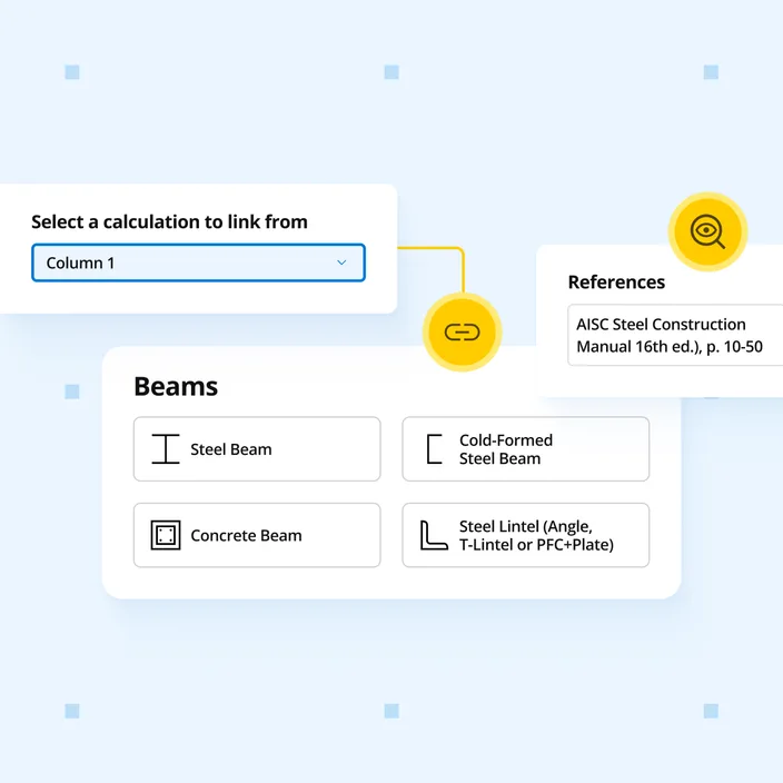
Beam reactions link to the columns and footings below, so load changes propagate downstream automatically. Design hot-rolled steel beams to AISC 360-16 LRFD with multiple spans and loads. Checks bending (Chapter F), shear (Chapter G), and three deflection limits with the governing load combination shown for each.
Who uses this calculator
Beam reactions link to your column and footing calculations automatically - change a load once and everything downstream updates. For US structural engineers designing hot-rolled steel floor and roof beams to AISC 360-16 using LRFD. For projects on the 2016 code cycle - use the AISC 360-22 LRFD version for new work.
How it calculates
The Steel Beam (LRFD, AISC 360-16) calculator performs a full LRFD strength and serviceability check on hot-rolled steel beams with any number of spans and loads.
Section classification (AISC 360-16 B4)
Before any capacity is computed, flanges and webs are classified as compact, noncompact, or slender based on width-to-thickness ratios (lambda) compared to lambda_p and lambda_r limits. Classification determines which capacity equations apply in Chapter F.
Flexural capacity - AISC 360-16 Chapter F
Positive and negative bending capacities are calculated separately. For compact sections the limit state is plastic moment: utilization = Mu / (phi × Mp) ≤ 1.0. For noncompact and slender sections, flange local buckling (FLB) and web local buckling (WLB) reductions are applied. Lateral-torsional buckling (LTB) governs when the unbraced length Lb exceeds Lp; the calculator interpolates between Lp and Lr and applies the Cb factor to account for moment gradient. The governing moment capacity is the minimum of yielding, FLB, WLB, and LTB limit states.
Shear capacity - AISC 360-16 Chapter G
Shear capacity uses the web shear coefficient Cv1 or Cv2 depending on web slenderness. For most W-shapes Cv1 = 1.0 and capacity is: utilization = Vu / (phi × 0.6 Fy Aw Cv1) ≤ 1.0 where phi = 1.0.
Load combination analysis
All ASCE 7 LRFD strength combinations are evaluated (1.4D; 1.2D+1.6L; 1.2D+1.6S+0.5L; etc.). The calculator runs FEA for each combination and identifies the governing case for moment and shear separately. Factored support reactions are reported for each combination.
Deflection checks
Three serviceability deflection limits are tracked independently:
- Instantaneous deflection - configurable as L/n or an absolute value; typically L/360 for live load on floor beams
- Long-term deflection - includes creep-amplified dead load and sustained live load; typically L/240
- Simplified DL+(LL or SL) deflection - combined dead plus live or snow for camber assessment
The critical (maximum) deflection across all unfactored load cases is compared to each limit: utilization = delta / delta_allow ≤ 1.0.
Inputs summary
Key geometry and section inputs: section designation, yield strength Fy (ksi), beam plan length, span lengths, support conditions, incline pitch, side length for inclined beams, and center-to-center tributary spacing. Load inputs: dead, live, roof live, snow, and wind loads as uniform, partial, point, or moment loads. Design criteria: individual deflection limit criteria for each of the three deflection checks.
Outputs summary
The summary panel reports critical moment demand and capacity, governing load combination for moment and shear, shear demand and capacity, maximum factored vertical and horizontal reactions, and all three deflection ratios. Support reactions are formatted for direct load linking to column and footing calculations below.