

What it calculates
Design and analyse timber beams with multiple spans and load cases to AS 1720.1:2010. ITI version with extended capabilities.
Who uses this calculator
Design timber beams to AS 1720.1:2010 for ITI workflows - moment, shear, and deflection checks with ITI-specific presets, Australian timber section defaults, and dynamic load linking to connected column calculations.
How it calculates
The ITI Timber Beam v2 calculator designs timber beams using Limit State Design per AS 1720.1:2010 Amendment 3. It runs a first-order elastic analysis to determine moment, shear, and deflection demands under each load combination, then checks those demands against AS 1720.1 design capacities adjusted for timber species, grade, moisture condition, load duration, and restraint.
Structural model
The calculator models the beam as a one-dimensional element and computes bending moment, shear force, and deflection diagrams under each load case. Loads are entered by type - permanent (G), imposed (Q), wind (W) - and governing ULS and SLS combinations are generated automatically per AS/NZS 1170.0 and AS/NZS 1170.1. For continuous beams with multiple intermediate supports, the moment and shear envelopes are evaluated across all spans simultaneously.
Bending capacity (AS 1720.1:2010, Cl. 3.2)
The design moment capacity phi × Md is determined from the characteristic bending strength and the relevant capacity modification factors:
phi × Md = phi × k1 × k4 × k6 × k8 × k9 × k12 × f'b × Z
Where:
- phi - capacity reduction factor (0.85 for bending per AS 1720.1 Table 2.1)
- k1 - load duration factor; ranges from 0.57 for permanent load to 1.0 for short-term imposed or 1.14 for wind
- k4 - partial seasoning factor, applied when member moisture content is between green and seasoned thresholds
- k6 - temperature factor for elevated temperature environments
- k8 - member restraint and stability factor accounting for lateral-torsional buckling of the compression edge (Cl. 3.2.5)
- k9 - factor for strength sharing in multiple-member systems
- k12 - stability factor for combined bending and compression (relevant in beam-column configurations)
- f'b - characteristic bending strength for the nominated species-grade combination (MPa)
- Z - section modulus (mm³)
The bending utilization check is:
M / (phi × Md) ≤ 1.0*
Stability factor k8 and lateral-torsional buckling (Cl. 3.2.5)
The effective length for minor-axis buckling is derived from the unbraced segment length and the end-restraint conditions. The calculator evaluates k8 automatically from the slenderness parameter S1 or S4 per AS 1720.1 Table 3.2. When full lateral restraint is provided to the compression edge (e.g. by a continuous floor diaphragm bearing on the top face), k8 = 1.0 and no buckling reduction applies.
Shear capacity (AS 1720.1:2010, Cl. 3.2.3)
The design shear capacity phi × Vd is:
phi × Vd = phi × k1 × k4 × k6 × f's × As
Where f's is the characteristic shear strength and As is the effective shear area (2/3 × b × d for rectangular sections). The shear demand V* is taken at the critical section, which is located at a distance d (depth) from each support face. The utilization check is:
V / (phi × Vd) ≤ 1.0*
Bearing capacity (AS 1720.1:2010, Cl. 3.2.6)
At each support, bearing stress is checked against the characteristic bearing strength f'p applied over the contact area. Moisture condition and load duration factors are applied consistently with the bending and shear checks.
R / (phi × Rpd) ≤ 1.0*
Deflection checks
Two independent serviceability checks are performed per span:
- Short-term deflection - instantaneous elastic deflection under imposed or wind loads, checked against a user-defined span/n ratio or an absolute limit in mm
- Long-term deflection - total deflection including creep under sustained permanent and long-term imposed loads, checked against a separate span/n ratio
Deflections are computed from the elastic bending stiffness EI of the cross-section. Load duration factors for the permanent load component follow AS 1720.1 Appendix B creep modification guidelines.
Load combinations
Strength (ULS) combinations follow AS/NZS 1170.0 Table 4.2 including 1.35G, 1.2G + 1.5Q, 1.2G + 1.5psQ + Ws, and wind-governing combinations. Serviceability (SLS) combinations use 1.0G + 1.0Q and 1.0G + 0.7Q for long-term deflection in line with AS/NZS 1170.1 Appendix C. The governing combination is identified for each check and reported alongside the utilization ratio.
Load linking
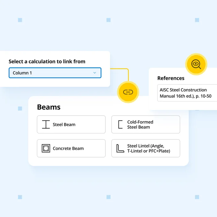
Support reactions are exported as linked outputs. Column calculators placed downstream in the same Calcs.com project - including the ITI Timber Column v1 - receive updated reactions automatically whenever beam inputs change.